


Source | CIRA, Petroceramics, ESA
I began writing about the Centro Italiano Ricerche Aerospaziali (CIRA, Capua, Italy) in 2024, discussing its work in carbon fiber-reinforced polymer (CFRP) lattice structures, but also the ceramic matrix composite (CMC) nose cone it displayed at JEC 2024 — reportedly the largest carbon fiber-reinforced silicon carbide (C/SiC) part produced to date using melt infiltration (see “JEC World 2024 highlights: Largest melt-infiltrated C/SiC part”).

CIRA displayed a melt-infiltrated ceramic matrix composite (CMC) nose for the Space Rider thermal protection system at JEC World 2024. Source | CW, CIRA, ESA
This 1.2 × 0.4-meter nose structure is a key part of the thermal protection system (TPS) for Space Rider, an end-to-end transport vehicle aimed to provide affordable and independent access to space being developed by the European Space Agency (ESA). About the same size as two minivans, the unmanned Space Rider will launch aboard a Vega C rocket to low Earth orbit (LEO) where its robotic laboratory will complete scientific and commercial missions for 2 months. It will then return to Earth and be reused up to six times, with minimal refurbishment in between. Space Rider’s inaugural flight is currently scheduled for 2027.


However, the story of CMC at CIRA is much larger than this single substantial part. The organization has been active in high-temperature materials for decades, and has been awarded the contract — in collaboration with partner Petroceramics (Stezzano, Italy) — to design, produce and qualify the entire Space Rider TPS comprising the nose, two body flaps for maneuvering during reentry, two large hinge TPS components that interface with the body flaps and 21 windward shingles including flat and curved tiles on the spacecraft’s belly, which also contain three sets for the landing gear doors.
This blog will discuss the patented ISiComp CMC and process used to make these TPS structures, their design and qualification, including CIRA’s high-temperature testing capabilities, and how CIRA’s Composite Prototyping Lab — which has played a central part in this complex project — envisions further developments in the future.
History of CIRA and Space Rider TPS


CIRA has worked on high-temperature ceramic, CMC and unmanned space vehicle (USV) technologies since 2000 and on the Space Rider TPS since 2016. Source | CIRA presentation December 2018 (top) and for HT-CMC11 in 2023 (bottom)
Since 2000, groups within CIRA have worked with the National Research Council of Italy - Institute of Science and Technology for Ceramics, CNR-ISTEC (now CNR-ISSMC) and Centro Sviluppo Materiali (now RINA-CSM) to study, develop and test ultra-high temperature ceramics (UHTC) and coatings. These groups completed winglet and nose structures and participated in multiple ESA projects to develop unmanned space vehicle (USV) technologies. This included the IXV intermediate vehicle, which flew in 2015. After this, ESA decided to build Space Rider.
“CIRA got involved in early 2016,” explains Dr. Mario De Stefano Fumo, deputy head of the space materials and hot structures unit at CIRA and CIRA’s system and technology manager for the CMC Space Rider TPS. “The company who manufactured the CMC body flap for the IXV decided to change their business. So, ESA needed a new manufacturer, and CIRA decided it could do this. ESA asked us to demonstrate our capabilities with a sort of preliminary qualification for Space Rider’s control surfaces, known as body flaps.”
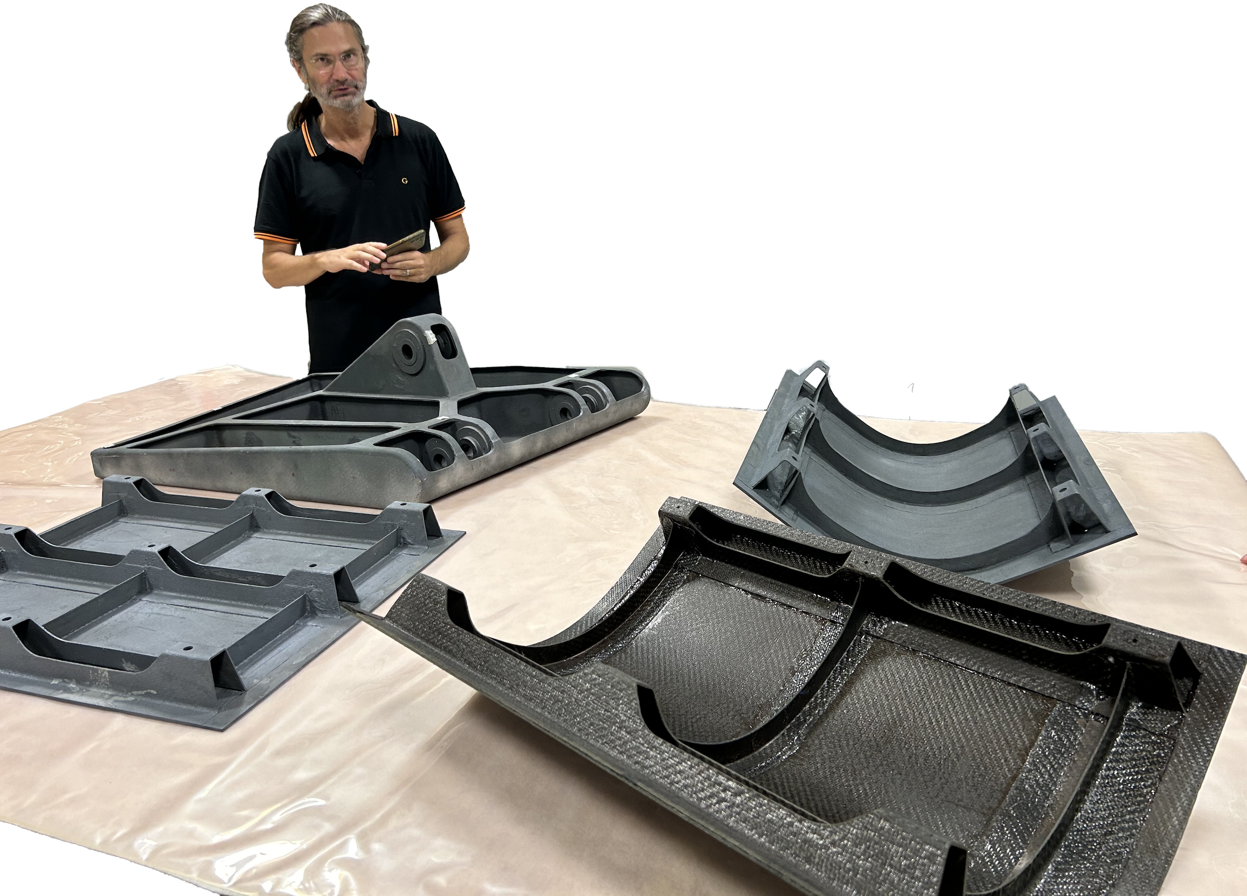

CMC parts for Space Rider TPS at CIRA (top) and process chain (bottom). Source | CW, CIRA
De Stefano Fumo explains that CIRA started this development with Petroceramics in 2016. “We had expertise in CFRP manufacturing while Petroceramics had ceramicization expertise because they had worked with Brembo [Bergamo, Italy] for CMC brake systems. They knew that the liquid silicon infiltration [LSI] process works well, but they had not built such large and complex C/SiC components before. Also, they typically worked with short fibers, not continuous fiber. We stepped from small ≈0.5-inch-diameter parts to larger components that were increasingly difficult to manufacture. In less than 2 years, we tested a 300 × 400-millimeter flap demonstrator with integrated stiffeners. It survived more than 1200°C for longer than 10 minutes in our Scirocco plasma wind tunnel [PWT] without any damage, demonstrating the CMC’s ability to withstand the aerothermal environment of reentry, as well as dynamic testing to simulate launch.”
The team completed a full review with ESA and were awarded the contract to design, build and qualify the body flap assemblies (BFA) for Space Rider in 2018. “But at that time, ESA and the prime contractor, Thales Alenia Space, also asked us to submit a quotation for the entire TPS made with our CMC,” says De Stefano Fumo. CIRA did so and proceeded with developing and testing a full-scale body flap measuring 700 × 900 × 300 millimeters in 2019. In 2020, it was awarded the contract for the full TPS.
“Since 2021, we have been designing, building and qualifying more than 20 CMC parts for the Space Rider TPS,” adds De Stefano Fumo. CIRA designs the CMC components and manufactures the CFRP preforms, which are then sent to Petroceramics for ceramicization into CMC parts and sent back to CIRA for qualification.
ISiComp CMC
Space Rider’s TPS uses a C/C-SiC material called ISiComp that CIRA and Petroceramics jointly developed and patented. It is made with a novel LSI-based process, reported to reduce manufacturing time and cost versus previous technologies. The ISiComp process comprises three steps:
- Manufacturing the CFRP part: Carbon fiber fabrics are impregnated with phenolic resin, shaped using prepreg hand layup and then cured in an autoclave to form a CMC preform.
- Pyrolysis: The preform is heated in a furnace to above 900°C, which carbonizes the phenolic resin, resulting in a porous carbon fiber/carbon matrix (C/C) green body.
- Siliconization: The C/C green body is heated above 1460°C in a vacuum and high-purity, low-viscosity, molten Si is injected, infiltrating the porous C/C microstructure and reacting with the C/C.
Petroceramics describes this process as yielding C/C–SiC materials that feature load-bearing C/C domains in a SiC matrix, creating robust internal protection against oxidation. The C/C–SiC material is further safeguarded against oxidation with an external SiC coating applied by Petroceramics in a proprietary process, enhancing its reusability.

ISiComp enables cost-effective manufacture of complex-shaped C/C-SiC parts in less time than with traditional CMC processes. Source | Petroceramics
“Of course, we didn’t invent LSI,” says De Stefano Fumo. “It has been known for decades. But we worked with Petroceramics to advance it for the production of these complex TPS structures. Our know-how was in designing the parts using continuous carbon fiber to achieve the necessary structural properties, while their expertise in pyrolysis and infiltration was critical in terms of managing the temperature and time at different steps.”
Managing shrinkage, tailored microstructure

ISiComp properties and scanning electron microscopy (SEM) showing microstructure tailored for good mechanical properties. Source | Petroceramics, CIRA
One of the key challenges in this CMC part manufacturing was managing dimensional stability, says Dr. Felice De Nicola, head of the Composite Prototyping Lab at CIRA. “When you pass from the CFRP to the ceramic, you must cope with shrinkage during both the pyrolysis and infiltration. Starting from a quite complex shape, which is already not easy to produce, we had to cope with the geometry changing during these steps, yet have the final part precisely meet a variety of requirements, including structural performance and assembly tolerances.”
This is a very important point, agrees De Stefano Fumo. “We had to design the components taking this into account because we have some shrinkage in both through-thickness and in-plane directions. We actually had to perform a sort of reverse engineering starting from the end, in order to build these preforms having already accounted for this.”

ISiComp samples exposed to a high enthalpy hypersonic flow (1250°C) for about 12 minutes x 6 times in CIRA’s Scirocco plasma wind tunnel (left) and atomic oxygen testing at ESA ESTEC (right). Source | CIRA
In a 2023 technical paper, Petroceramics credits ISiComp’s properties to this tuning of pyrolysis and infiltration to control shrinkage, deformation and the fiber-matrix interface, resulting in a tailored microstructure. With a bending strength of 250 megapascals and tensile strength of 170 megapascals, ISiComp was designed to withstand extreme thermo-mechanical stresses up to 1650°C.
To simulate six atmospheric reentry flights, two test campaigns were conducted at different temperature levels, each totaling six cycles: one at 1250°C for 70 minutes and another at 1450°C for 85 minutes. After this testing in CIRA’s Scirocco PWT for all six cycles, material samples showed negligible mass loss (0.3%) and scanning electron microscopy (SEM) analysis confirmed good coating performance and no fiber oxidation, while residual strength was similar to values from virgin samples. ISiComp has also passed outgassing and thermal vacuum testing as well as exposure to atomic oxygen plasma.
Prepreg and layup know-how
For the CFRP preforms, CIRA has used intermediate modulus carbon fiber and phenolic resin made into a prepreg. “We use fabric prepreg for almost all the parts because we don’t need unidirectional properties and the fabric is helpful to form the shape,” explains De Stefano Fumo. “For the resin, we tested many phenolics and selected the one that worked best for us. It’s a commercial product, but we did tailor some aspects to improve the complete manufacturing route.”
Phenolic resin was chosen because it produces significant carbon during pyrolysis — it has a high char content — to form the C/C green body. “This is fundamental for the ceramicization process and the final product,” says De Stefano Fumo. “And after pyrolization, you have some porosity and cracks in the preform, which is essential for the subsequent Si infiltration. Thanks to these cracks generated inside the matrix during pyrolysis, the melted Si can infiltrate inside the carbonized preform. However, the cracks need to have the right size, because if they are too small, Si cannot infiltrate and if they’re too large more Si can remain unreacted, decreasing the performance of the finished CMC.”
However, De Nicola points out that his lab’s expertise was in CFRP structural design and layup, not in ceramicization. “The whole team had to learn about the pyrolysis and infiltration process and work with Petroceramics to understand it,” he notes. “And a key piece of what makes these CMC parts successful comes from Paola.” Here, he refers to Paola Spena, manufacturing engineer in CIRA’s Composite Prototyping Lab. “She developed the layup concepts and tools, working with the design team to create the CFRP preforms.” He notes that finding the best solution for each CMC part required iteration. “We needed to produce parts to see the changes during pyrolysis and infiltration and then understand how to optimize a combination of parameters. The know-how we have developed includes not just the raw materials, but the layup schemes and lamination procedures for the CFRP preforms. And now we are developing a lot of experience with testing and correlating properties between the preforms and finished CMC.” We’ll come back to that below.
Machining and coating
We now return to the issue of meeting assembly tolerances. “To do this, we pre-machine the autoclave-cured CFRP,” says De Stefano Fumo. “And then after pyrolysis and infiltration, there is a final machining of the CMC parts, completed by a dedicated provider that has expertise in CMC machining.” He notes there are a lot of companies with such capability in northern Italy thanks to the Motor Valley and Emilia-Romagna Region, famous for numerous automotive and motorsports companies.

SEM and energy dispersive X-ray spectroscopy (EDX) show the SiC coating (red) and thin silica layer (green) on top. Source | CIRA
And, as mentioned above, the final step in the ISiComp process is coating for oxidation resistance. This is another patent developed by CIRA and Petroceramics. “This is a different approach that exploits aspects of LSI to achieve a sort of physical deposition,” says De Stefano Fumo. “We grow a SiC layer on the top of the components. It is not really a coating because we have a dentritic structure between the SiC coating and the structure underneath, and this enhances the joining and the oxidation resistance of the components.”
In CIRA’s December 2018 technical presentation, analysis after the six cycles of PWT testing to simulate reentry noted that the coating on the external side covered the entire surface with a thickness of ~50 micrometers and no signs of active surface oxidation. The chemical map developed through SEM and energy dispersive X-ray spectroscopy (EDX) showed oxidation effects only on the external part of the coating, an inner layer of compact SiC about 20 micrometers thick. The tests also noted no oxygen was found at the SiC throughout the CMC and also no free, unreacted Si, which could increase the risk for oxidation, crack initiation and other degradation.
De Stefano Fumo adds that even though this coating is a postprocess step, it reduces overall manufacturing time and cost versus vapor deposition. “For example, depending on the size and complexity, you can have a final complex CMC part in a few weeks, and it’s already protected against oxidation.” It can be also reapplied between missions, key for Space Rider’s reusability.
Nose and BFA
Before discussing topics such as in situ joining and qualification, let’s look at the TPS structures. Although the nose and BFA each presented challenges, they were based on very different concepts.

The largest TPS structure is the double-curved, non-axisymmetrical CMC nose with 16 cobonded, omega-shaped CMC attachment points around the perimeter. Source | CIRA
The nose is the largest single part (1,320 × 941 × 414 millimeters) and takes the majority of the temperature during reentry but is attached to a substructure that carries mechanical loads. “This is exactly how the nose worked on the Space Shuttle,” notes De Stefano Fumo, “except there was no insulation between the CMC and substructure, while for Space Rider we do use an insulation stack that lowers the temperature from above 1400°C on the CMC to 160°C for the cold structure beneath.”

The BFA comprises two flaps with integrated stringers and three attachments points: two hinge points and one point where the electromechanical actuator (EMA) arm attaches. Source | CIRA
In contrast, each BFA is a 700 × 900 × 300-millimeter contoured aerodynamic control surface without insulation but with integrated stiffeners to carry load. “These also had the most complex CFRP preforms,” says Spena. “We made the body flap first, and then the nose.”
“The body flap is hinged to the vehicle at two points,” explains De Nicola, “and there’s also an arm that moves the control surfaces up and down during reentry. Thus, its aerodynamic load is completely concentrated in these three points.”
“For the nose,” says De Stefano Fumo, “the loads are homogeneously distributed between 16 omega-shaped attachment points. Its design and manufacture is not necessarily easier than the body flap, but the body flap has more structural and geometric complexity because you have a lot of internal stiffeners and cavities to take into account.”
Layup for the CMC nose used a standard approach, says Spena. “We made the preform and that is basically what you see after ceramicization, but the flap we designed as several CFRP parts that had to be joined. We cobonded all the stiffeners during the CFRP manufacturing but the triangular part where the rod for the actuation attaches — what we call the ‘shoe’ — that was made as a separate CFRP part and in situ joined during infiltration at Petroceramics. Although the nose uses the same material, same steps and same basic layup process as the flaps, placing the prepreg plies was tricky because it’s a large, double-curved surface that is not axisymmetric and does not have a homogeneous thickness. The 16 omega-shaped attachments were also cobonded around the perimeter of the nose skin during the CFRP manufacturing.”
Both of these TPS structures are connected to the cold structure underneath through metallic attachments called stand-offs. These are subjected to critical mechanical loads during launch and critical thermal loads during reentry. For the nose, the 16 omega-shaped CMC attachment points connect to Inconel standoffs with Inconel screws and zirconia insulators between the CMC and the screws. Sigraflex washers manage any surface roughness and disk springs maintain necessary preload during reentry. The starboard and port BFA connect to the vehicle structure using additive layer manufacturing (ALM) titanium (Ti)-alloy supports and high-temperature bearings while the arm/electromechanical actuator (EMA) is relayed to the flaps via Ti-alloy EMA rods.
Windward shingles, hinge TPS

Space Rider’s windward TPS comprises flat, curved and double-curved shingles with omega-shaped stiffeners and T-shaped ribs. Source | CIRA
Space Rider’s windward TPS comprises five flat shingles, 16 curved shingles and two large hinge TPS structures. Three sets of shingles accommodate landing gear door openings. The windward shingles use omega-shaped stiffeners and T-shaped ribs as well as insulation. Their attachment system is designed to withstand pressure and dynamic loads while allowing thermal expansion.
There are also two hinge TPS that protect the areas where the port and starboard BFA flaps are attached. Two cutouts for the ALM Ti-alloy support rods and a notch on the top edge provides room for the EMA rod pass-through. The latter is sealed with a rigid sleeve and a bellows made from Saffil alumina fiber (Alkegen, Buffalo, N.Y., U.S.) encapsulated in Nextel alumina fiber (3M, Minneapolis, Minn., U.S.) for insulation and movement.

Hinge TPS. Source | CIRA
Like the BFA and nose, the shingles also feature a very complex attachment system using metallic fasteners and zirconia thermal washers, as well as Sigraflex foil (SGL Carbon, Wiesbaden, Germany) to reduce the maximum temperature from about 700-800°C, which is what the Inconel 718 fasteners can withstand, to ~130°C for the vehicle’s CFRP skinned aluminum honeycomb cold structure underneath. “Then inside this shingle, there are a lot of insulator pillows using alumina and silica fibers,” explains De Stefano Fumo. “The outer surface of the vehicle can achieve 1600°C, so we must stop this from reaching inside. So, we also seal between the different shingles.”
In situ joining

The body flap assembly (BFA) features the triangular shaped “shoe” for the actuation rod attachment, joined during the infiltration step at Petroceramics. Source | CIRA, Petroceramics
As mentioned above, this technique is one of the benefits offered by the LSI process and was used by CIRA and Petroceramics to achieve the complex BFA structures. “This kind of joining during Si infiltration is well known,” says De Stefano Fumo. “Even if you consider just the flap as a CFRP structure, it is very complex. As Paola explained, we joined some of the stiffeners to the flap during the CFRP manufacturing. We developed the tooling to produce that part and then produced the other CFRP green bodies, like the triangular shoe, separately and sent these to Petroceramics to be joined during LSI. There are also bearing components made by Petroceramics where we have the three points attachments for the flap, which are also integrated during LSI.”
Why join the shoe using LSI instead of cobonding like the stiffeners? “Because it’s a larger part,” says Spena. “At the beginning, we were worried about the shrinkage, so we preferred to make it separately and machine after pyrolysis to ensure it fit with the boxes inside the flap. We then joined it during infiltration.
“We developed tooling to produce all the green bodies and then Petroceramics developed different tools for pyrolization and infiltration,” she continues. “It’s very important to have the right alignment of everything during the in situ joining. So, there must be precision in the position of the mold. And once the part has been produced, there is final machining just to be precise in the alignment for the assembly surfaces.”
Design and simulation
The discussion about in situ joining led to one about the complexity of these TPS parts and how long it took for CIRA to complete the design for manufacturing. “The preliminary design took several months,” says De Stefano Fumo. “Then we worked in parallel with Paola and Petroceramics for the manufacturing. We changed the manufacturing chain at least two times, and in the meantime, we adjusted the design. But we actually didn’t have much time due to when the demonstrators were due. We started the contract at the end of 2018 and the first full item was manufactured in 2019. We manufactured three demonstrators total, and the last one we successfully tested in static and dynamic test campaigns.”

CIRA used mostly commercial FEM/FEA tools but also compared results from different tools as the knowledge base for CMC is still low. Source | CIRA
The design and simulation software used were mostly commercial tools, including Nastran, Abaqus (Dassault Systèmes, Vélizy-Villacoublay, France) and Ansys WorkBench (Ansys, Canononsburg, Pa., U.S.), able to simulate both thermal and mechanical loads and thermostructural performance, says De Stefano Fumo. “There is not that much widespread knowledge yet on CMC design tools, so it was important for us to compare the results coming from different numerical tools.”
For each component, a full set of FEM analysis was performed:
- Unsteady thermal analysis along different reentry trajectories (3D FEM)
- Steady state thermomechanical analysis with combined load (temperature, pressure, inertia - 3D FEM)
- Static structural analysis (QSL, Eq Sine DLL - 2D Shell)
- Dynamic structural analysis (Modal, Sine, Random - 2D Shell)
Additional analysis:
- Draping/manufacturing (2D Shell)
- Material simulation
- PWT testing (in-house 3D NS code with NEQ Chemistry)
“The problem was and still is to have the real properties of the material as manufactured,” notes De Nicola. “The manufacturing process is quite complex, and the material has different peculiarities and characteristics depending on the part. We have completed an experimental campaign to test the material, and we are following the standard building block approach used in the aerospace industry. We started from the materials characterization at the coupon level, then moved to the sub-element level, and kept increasing the complexity of the parts.”

CIRA used a standard aerospace industry building block approach to characterize ISiComp. Source | CIRA
However, compared to metals and traditional CFRP, there is more complexity in modeling the CMC materials, he explains. “So, we need a lot of experimental tests in order to improve the knowledge about the material and also to really understand how the material and the components works under the loads.”

Many ISiComp coupons were tested to establish A-basis and B-basis allowables. Source | CIRA
“Even to do the beginning design work, we had to make all those material test coupons,” says De Stefano Fumo. “We started by looking directly at the CMC properties. However, in the last months, we have started to work on some activities to better correlate the CMC behavior with the CFRP performance.”
“But at the beginning, we did not have enough time to start this kind of research,” notes De Nicola. “Our first concern was how the initial dimension would translate to the geometry of the final CMC parts. We produced so many flat CMC coupons, varying the pressure, temperature and other process parameters to understand the material behavior and reduce possible variation in thickness. We had to understand the CMC properties to give to the design team.”
He points out that pyrolysis actually destroys the properties of the CFRP. “So, its main contribution is how the material is compacted and the char yield in the pyrolized part,” says De Nicola. “The CFRP is just a means to achieve a porous green body that you infiltrate. For example, one of the main problems is the pull out between two parts that are in situ joined during infiltration. This is occurring in the CMC, so you want to understand how the two parts are linked together with that material, not the CFRP.”
De Stefano Fumo cites another issue. “Shrinkage during pyrolysis and infiltration may cause residual stress inside the material, causing deformation during the process that you have to manage. So, you must know what happens during the process to understand much better the material behavior and performance. This is why we are starting now to correlate the properties of the CFRP to the CMC. Note, thermal deformation also happened during the cure of the CFRP. We must also understand this, for example, if we are cobonding in the CFRP phase we must be sure this is strong enough to withstand deformation during subsequent pyrolysis and LSI.”
Qualification, future developments
Qualification testing for the Space Rider TPS structures is ongoing at CIRA, with completion targeted for the end of 2025. In fact, CIRA is recognized worldwide for its aerospace and space systems qualification capabilities. Its Scirocco PWT, in operation since 2002, is the largest in the world, reaching Mach 16 with a stagnation temperature up to 10,000°C and a maximum test period of 25 minutes. It is equipped with a 70-megawatt arcjet and can test samples up to 0.6 meters. CIRA’s smaller Ghibli PWT can reach the same test conditions and duration but uses a 2-megawatt arcjet for samples up to 80 millimeters.
CIRA’s Space Qualification Lab accommodates testing of small spacecraft and assemblies and complies with the ESA standard ECSS E-10-03-A “Space Engineering – Testing” and MIL-STD 810F including:
- Physical properties measurements
- Acceleration test
- Vibration and temperature (“shake and bake”) test
- Combined vibration, humidity, temperature and altitude test
- Environmental stress screening
- Thermal shock test
- Thermal vacuum test
- Pyroshock test.
It also has a large ice wind tunnel, used to develop and qualify de-icing systems for aircraft and rotorcraft.


CIRA is completing qualification testing for all of the Space Rider TPS structures, including thermomechanical testing of the BFA hinge attachment (top) and shingles attachment (center) plus static and dynamic testing such as for the BFA shown here (bottom). Source | CIRA
For the Space Rider TPS, CIRA has manufactured full-scale qualification models for the nose, BFA, hinge TPS and four different windward shingles. Other test articles include sub-scale modules of shingles integrated together with their attachment systems to demonstrate their ability to withstand reentry in PWT testing.
However, for CIRA, the most critical phase of the mission is not reentry, says De Stefano Fumo, but launch. “Because ISiComp’s structural performance has been established as well as its ability to withstand temperatures up to 1600°C with no issues, we are not so worried about static or thermal loading. But the dynamic, vibrational environment at launch is very critical for this kind of material. So, qualification also includes an impressive campaign with sine, random and shock loading to verify these structures can withstand not only one launch, but six.”
A combination of mechanical and thermal load is applied using a dedicated furnace installed on a mechanical test machine to verify that the attachments not only handle preload without issue but continue to handle all required loading after six cycles. Visual inspection afterward showed no damage or degradation in any part of these attachment systems.
“We have also had to manufacture some sub-scale components for our plasma testing, because despite Scirocco being the largest PWT in the world, the full-scale qualification models are still too large,” notes De Stefano Fumo. “These reduced-scale components are fully representative of the flight hardware, and we have used these to verify the performance of the interfaces between the CMC parts, metallic parts and insulation in the reentry environment.”

The ISiComp and Composite Prototyping Lab team at CIRA responsible for the design, production and qualification of the Space Rider TPS. Source | CIRA
All qualification models have been manufactured, and efforts are now focused on completing the various types of tests. In parallel, the production of tools and molds for the flight hardware is ongoing, with the manufacturing of initial components expected to begin before the summer.
“We are thrilled to be building flight components and contributing to the Space Rider mission,” says De Stefano Fumo, “especially considering the years of dedication and hard work from the entire team. At the same time, we are already looking ahead to the next challenges for ISiComp.”
CIRA is actively involved in several initiatives aimed at advancing European reusable launchers, he adds. “While SpaceX has successfully demonstrated the reuse of a first-stage launcher, the challenge of second-stage reentry remains unresolved, as evidenced by Starship’s setbacks,” he notes. “Therefore, our next objective is to use ISiComp to design the thermal protection systems and control surfaces for reusable upper stages.”


Related Content

A new era for ceramic matrix composites
CMC is expanding, with new fiber production in Europe, faster processes and higher temperature materials enabling applications for industry, hypersonics and New Space.
Read More
Arceon introduces novel CMC materials for space, defense
Carbeon C/C-SiC ceramic matrix composites are being developed and tested for rocket nozzles, onboard the International Space Station and in electric aviation, metal treatment and reactor applications.
Read More
Bombardier begins manufacture of Global 8000 business jet
Ultra-long range business jet featuring CMC-intensive engine and a range of 8,000 nautical miles is set to enter service in second half of 2025 as it remains on track for flight testing.
Read More
New CMC turbine vanes successfully tested in wind tunnel
SiC/SiC ceramic matrix composite (CMC) inlet guide vanes for a high-pressure turbine are aimed for a geared turbofan and show promise for more efficient aeroengines with less weight and need for cooling.
Read MoreRead Next

Low-cost, efficient CFRP anisogrid lattice structures
CIRA uses patented parallel winding, dry fiber, silicone tooling and resin infusion to cut labor for lightweight, heavily loaded space applications.
Read More
Near-zero erosion ultra-high temperature CMC
K3RX commercializes UHTCMC for a wide range of markets, demonstrating performance in prototypes, assemblies and advancing manufacturing to reduce cost.
Read More
Post Cure: Parallel winding technique demonstrates CFRP anisogrid design optimization
Over the years, CIRA has demonstrated its patented CFRP parallel winding technique in a variety of ways for space applications. The lattice structure for the Vega-C launcher stage is a prime example.
Read More